UKMARS bot
__________________________

History
In the past we have used PicAxe based robots to teach and entertain students in the art of Robotics…
We have used robots to draw patterns, avoid obstacles, follow walls and lines, and win drag races.
________________________________________________
Uses
We will use the robots to teach simple python methods of
Input, (analogue and digital)
Output, (PWM and on-off)
Decision making,
Maths to generate output values ,
Also the Use of constants, functions and objects to simplify the code.
Also comments, and code management.
So to sum up we will use the UKMARSBOT for
- Flashing LEDs,
- Drawing patterns,
- Line Following
- and Drag racing
________________________________________________
Teaching
We will teach the following …
1) Python programming, Thonny IDE
2) Electronics: switches, resistors, LEDs.
3) input and output: Digital and analogue.
4) programming fixed manoeuvres
5) programming responsive manoeuvres (feedback)
6) Tuning, and Competition-thinking
________________________________________________
| - use the raspberry Pi Pico as controller - This requires a 5-volt regulator, which we have mounted on a board under the Pico |
 |
| using the 4-way Switch as 4 digital inputs. | 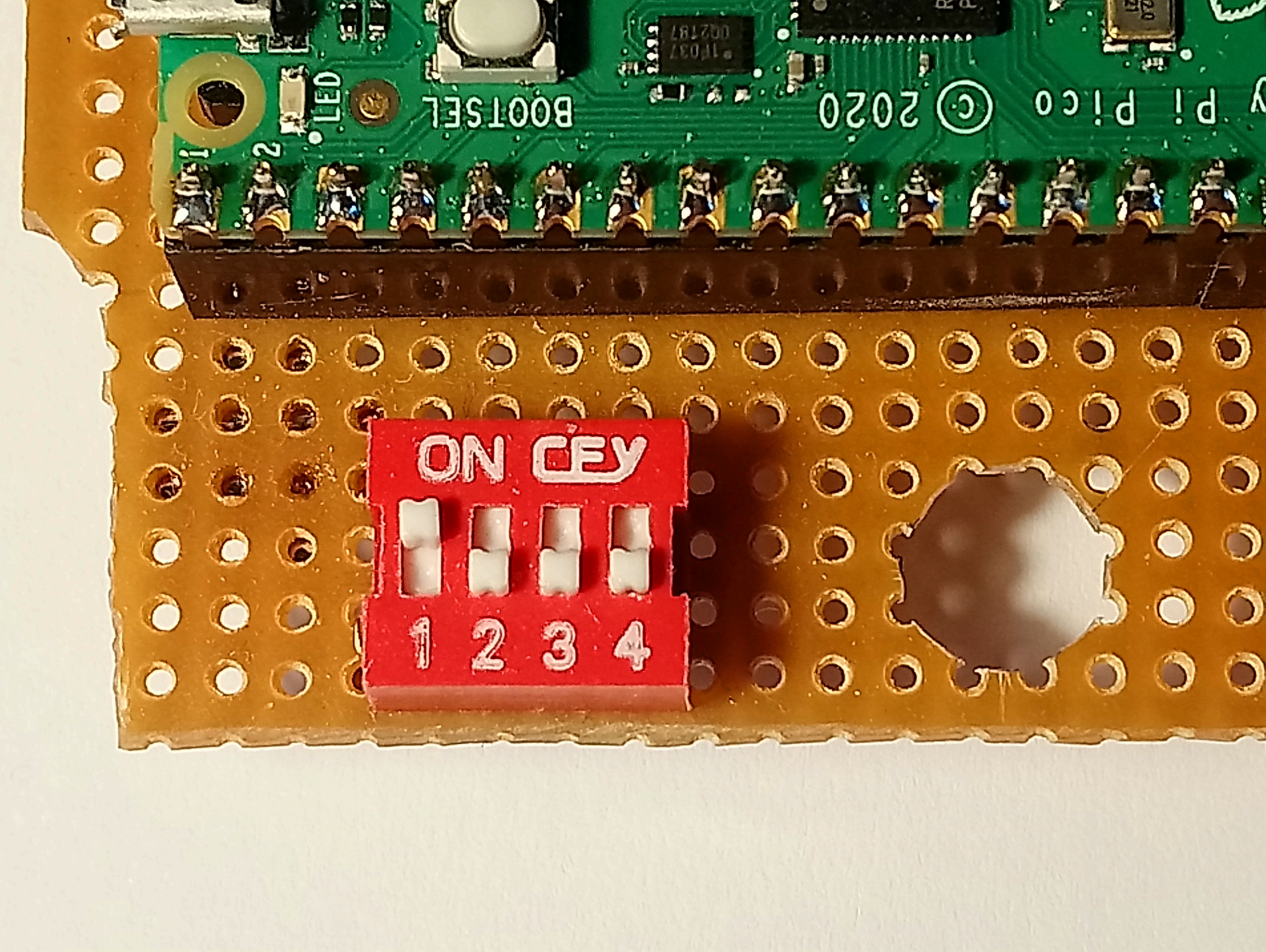 |
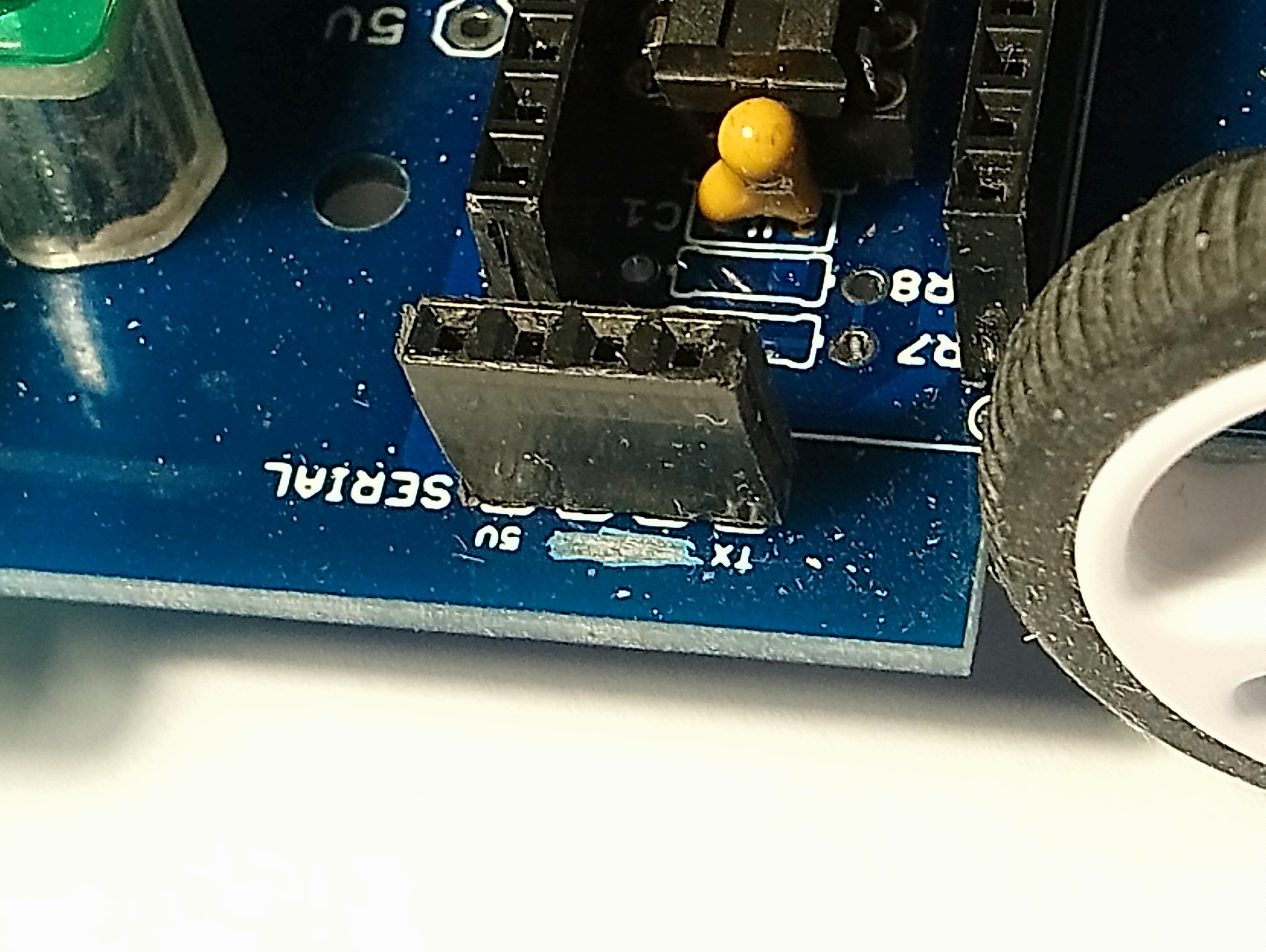
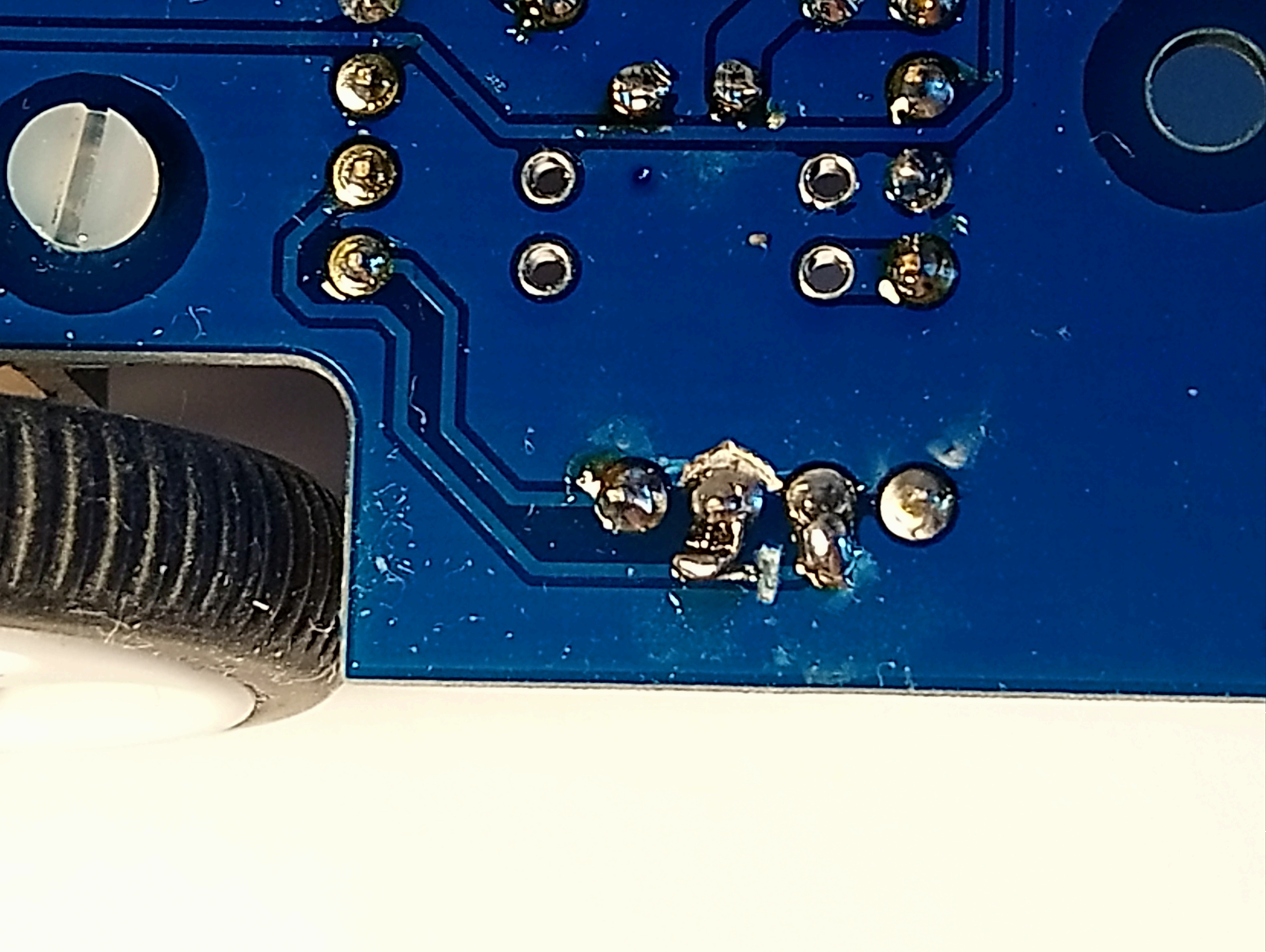
| We have adapted the serial connection to accept an HC06 bluetooth adapter, by swapping the TXD and Gnd pins on the socket where it plugs in. The underside view of the socket: : |
 |
- we run the line sensor off 3.3volts, to make its outputs compatible with Pico.
- We have arranged for the motor driver to be run (optionally) off the 5volt supply
rather than the raw battery voltage. This should make drawing polygons more reliable.
9 volts would be better for a drag race.
- not using the battery voltage measurement
- not using the analogue function selection switch (16-way)
- not use the motor encoders, although a distance measure would be good for the drag.
We have developed an infrared TV remote receiver module for remote control
and for in-flight parameter adjustment.
The TV remote module is shown below with an HC06 Bluetooth module:
We have drilled a hole in the chassis between the motors so that a pen can be slotted down to draw patterns. There is also an upper hole in the Pico circuit board
________________________________________________
Software
We use a Motor object to hide the Motor driver complexity
We store the tuned parameters (speed proportion etc) in a single python file, which can then be re-imported on switch-on.
Interactive control via Bluetooth, and TV remote. This will let the students see the immediate effect of adjusting line follower parameters.
TV remote doesn't require a mobile phone or laptop, but also allows broadcasting the same signal to all the robots in the room! This can give fun synchronised displays. (see video below)
TV remote doesn't let the robot send data back unfortunately. (unlike Bluetooth )
There is also an upper hole in the Pico circuit board
Line Sensor
We 'calibrate' the Line sensor values by recording maximum and minimum values,and producing a value in the rangle 0-99.
We have addressed the Line sensor position calculation, based on David Hannaford's original program..
and have arranged for detection of falling off the line, remembering which side we fell off.
| The Line sensor position. Calculating the position from the 2 sensor outputs can be improved |

|
| - The original computation of Left-Right give a limitited range. |  |
| We have divided it up into 3 ranges - central : use Left-right - Left of centre: use Constant-right - Right of centre: use Left+Constant where constant is calulated for the value of the remaining sensor, wnere the other fell off the line. |

This gives a wider almost monotonic region. |
Finally: a bit of fun with the TV remote... The digits 1-9 control a pre-set manoeuvre. Video: